Plasma pipe cutting is a high speed cutting technology developed to cut electrically conductive materials. In this article we will explain all the basics for plasma pipe cutting.
Plasma cuts through electrically conductive material by an ionized arc which is blown out of the nozzle. This vaporizing arc is created by an electric circuit between the material and the torch. The torch of conventional plasma equipment emits a protective gas around the cutting gas which insulates the nozzle from spatter during piercing and it further improves cutting quality. High definition plasma equipment narrows the arc by a special torch design. This results in an increased energy density of the arc for superior cutting quality.
Cutting gases can vary
Depending on the selected plasma equipment, the cutting gases can vary between air or optionally oxygen, hydrogen nitrogen or argon. Also dependent on the cutting gasses the shield gases can vary between air or optionally nitrogen.
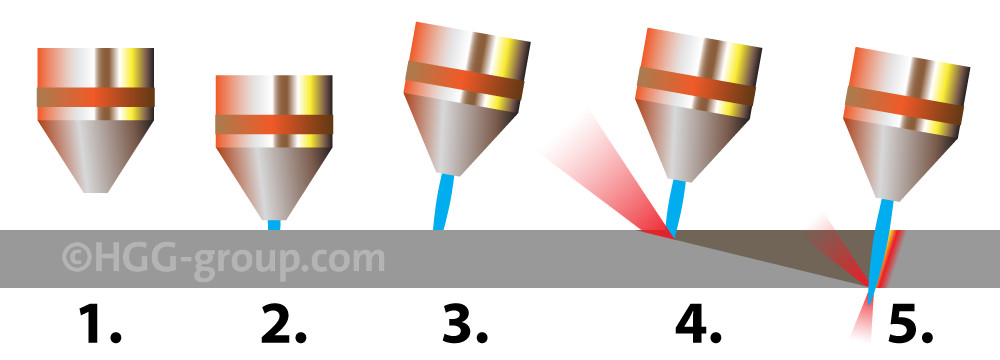
Angled piercing
- The piercing sequence starts with torch positioning at the start of the lead-in.
- Now the torch lowers to pierce height. The plasma torch creates a pilot arc which will be blown out of the nozzle by a gas stream providing a pathway to ignite on the conductive raw material. The main arc is created once the pilot arc hits the raw material.
- The torch moves up to be ready for piercing. The torch angle can be specified as well for specific applications.
- A current ramp-up follows to start the piercing process while the torch starts to move towards the initialisation point of the profiling shape and the perfect torch-to-material distance for cutting. The optimised angle, height and movement of the torch during piercing prevents the nozzle from spatter to achieve a longer consumable lifetime.
- After piercing the torch is at the correct bevel angle to start the actual cut.
Characteristics of Plasma Pipe Cutting
Versatile
Plasma cuts through any electrically conductive material, allowing the cutting of a wide range of materials from mild steel to exotic alloys.
Fast
In the wall thickness range up to 25 mm, plasma cutting outperforms oxy fuel cutting. The exothermal process of oxy fuel cutting limits the cutting speed to between 350 and 800 mm/min. whereas plasma pipe cutting can reach speeds of up to 3000 mm/min. with smaller wall thicknesses. Because plasma cutting requires no pre-heating, even more time is saved on each individual cut.
High quality
Plasma cutting delivers a superior surface result than oxy fuel when cutting thinner material. Plasma also has a smaller heat-affected zone resulting in less distortion of the material’s microstructure.
Plasma costs
Initial investment costs are higher for plasma than for oxy fuel. This is because, apart from the plasma source, a complete exhaust system with filtering unit is required. The cost of monthly consumables is also more expensive than oxy fuel but this is compensated by the higher cutting speed increasing production.
HGG’s unique plasma features
HGG’s pipe cutting machines and software allows for the following compensations of plasma characteristics which are unique to the industry and only available with HGG’s machinery, made possible due to the fact that all software is developed by HGG in-house.
Torch-to-material distance control
This technique maintains a constant distance between the torch and the material after measurement of the material surface. It helps to prevent cutting torch collisions, cutting deviation and ensures a constant arc.
Kerf width compensation
Kerf width compensation is included in all CNC pipe cutting routines to compensate the arc thickness which ensures accuracy.
Arc shape compensation
The greater the wall thickness of the material, the more the shape of the arc can influence the accuracy of the cut. This is an angular compensation to correct inaccuracies due to arc convergence.
More about compensation for plasma beam in the article ‘How to Compensate for Plasma Beam?’
Plasma Technology
Want to know everything about plasma technology? Read the article ‘Understanding Plasma‘ on the website of plasma technology specialist Hypertherm.


