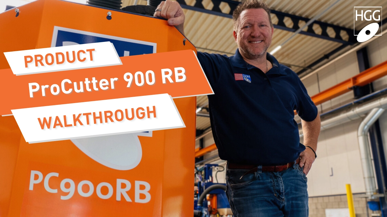
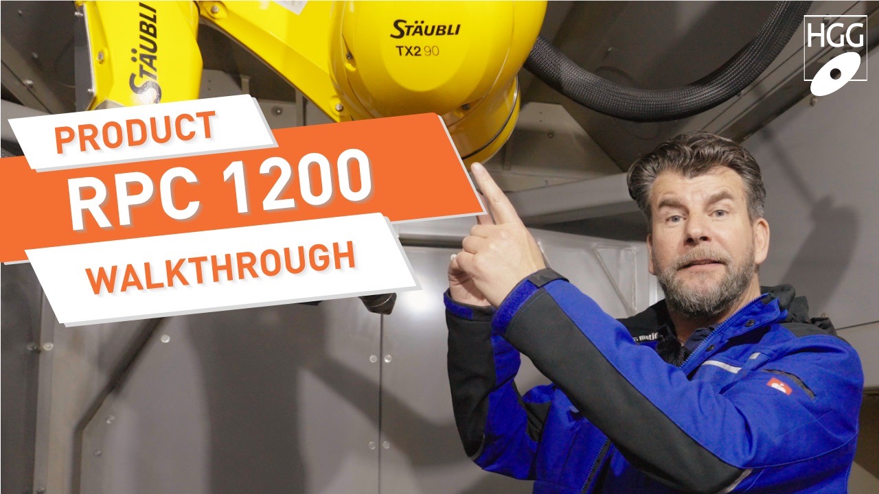
Being a hi-tech designer in the process piping industry, you probably use a CAD-system, like Spoolgen, to design and detail your models. Not having your CAD-system connected with your pipe cutting machine, means a lot of time consuming manual programming of data for you.
Together with Spoolgen, HGG 3D Profiling developed a CAD/CAM interface for a seamless integration between your Spoolgen and HGG cutting machines. Your models, created by use of the CAD-system, are the source for HGG’s CAD/CAM interface.
Design & Detailing
Spoolgen is a powerful CAD system to design spools. The centerline based design method offers fast creation of any design. The Spoolgen detailing module contains ‘Profiling shapes’. These tools developed by HGG are representing a type of connection like ‘chamfer’ and ‘saddle’ and have parameters to define the weld preparation of a connection. Including parameters for root opening and shrinkage. A profiling shape with the chosen connection and weld preparation type can be applied on a specific intersection. All intersections of the model need to be detailed with profiling shapes to guarantee complete extraction of design data.
Post-Processing and Data Export
Using the post-processing functionality in Spoolgen’s Detailing Module enables you to convert designed and detailed parts containing cuts and markings to .PCD-files.
Cutting Path Calculation
HGG’s ProCAM recognizes the type of material, shapes to cut and the weld preparations (if detailed) automatically. The lead-in and lead-out of every cutting path will be automatically applied. The 3D Viewer gives a live view of the imported part, which can be used during nesting as well. After nesting a cutting file can be generated for cutting of the full raw material length at once.
